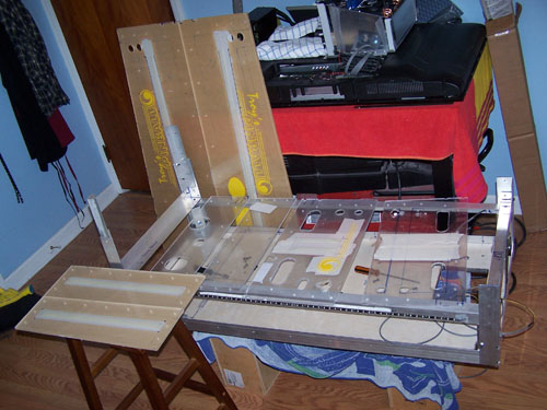
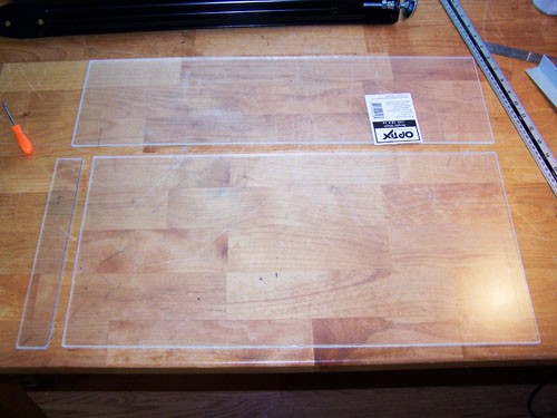
Here is the entire thing completely disassembled, the
panels were cleaned up and all the masked edges were tamped, so it's
ready to spray.
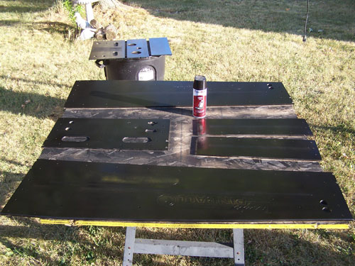
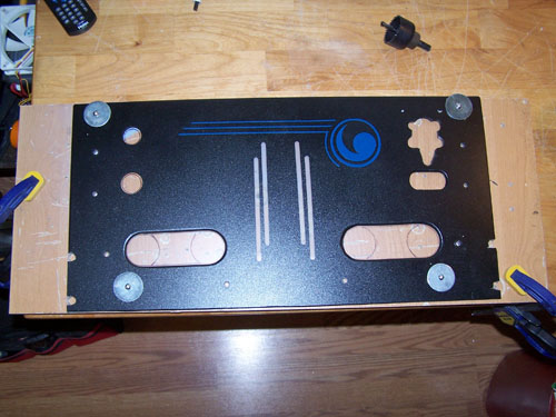
Below shows what the acrylic panels look like after
the first coat of black vinyl color.
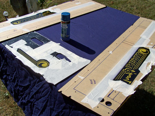
Three cans later and the front side of each panel was
sufficiently black. The backs of each panel were masked and
then sprayed with blue vinyl color behind the vinyl decals.
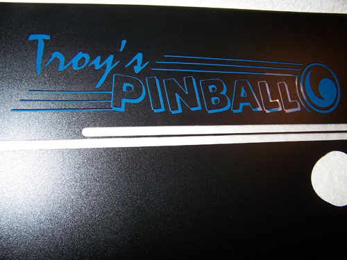
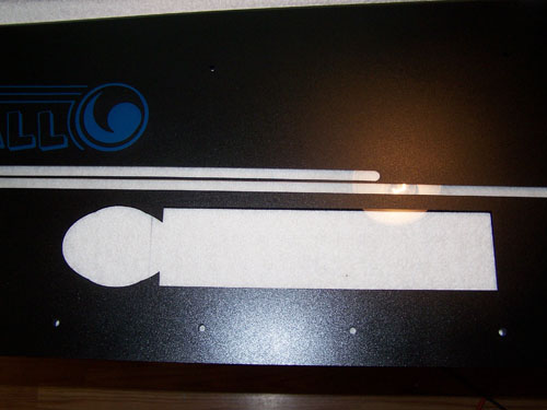
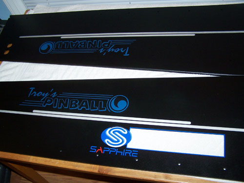
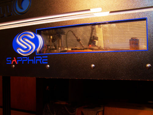
Here it is with the all the masking removed, the
shiny smooth blue letters look killer against the finely textured
black surface.
Sapphire rocks and so does their window outline,
vinyl sign material makes a great mask when used with automotive
vinyl color, I didn't have color seep under the mask anywhere.
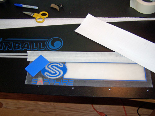
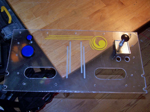
Time to install the Sapphire decal I had made, I
lined it up and taped it along the top edge, then removed the
backing paper and used the blue card to smooth it down.
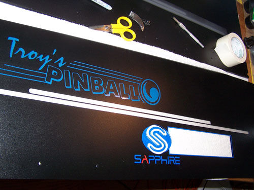
It looks good, but I still have a little more to do
on the back sides of the panels before they can be installed.
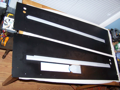
I cut the roll of light diffusing film into strips
and black electrical taped them onto the inside panels over the SMD
LED strips location, then I brushed all of the taped edges with
liquid electrical tape to make sure they stay put. A piece of
light diffusing film was also cut to fit over the Sapphire "S", it
will also be getting some glow treatment.
Both side panels are finished and ready for
installation... I still can't believe how nice they turned out.
It took a lot of patience and cans of vinyl color to
get all the panels looking right, but at $9 a can I wasn't so
worried about the back, if it looks a little splotchy it's because
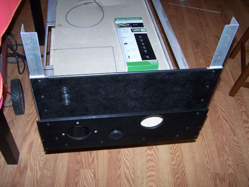
it is. I vinyl colored the duct to the PSU black and screwed
it onto the now ready for install back panel.
Front panel unmasked and ready to install.
I am putting the back box together first, get those
pieces together and out of the way so I can focus on the table part
of the build... not far now.
The back box is assembled, now to put the side panels
onto the table starting with the back. I also bought a seven
outlet surge protector for the inside of the cabinet to replace of
the six outlet adapter type I had originally planned to use.
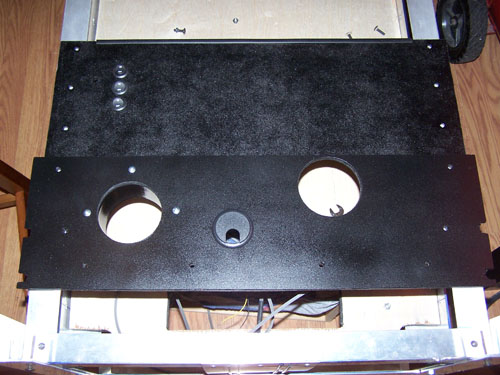
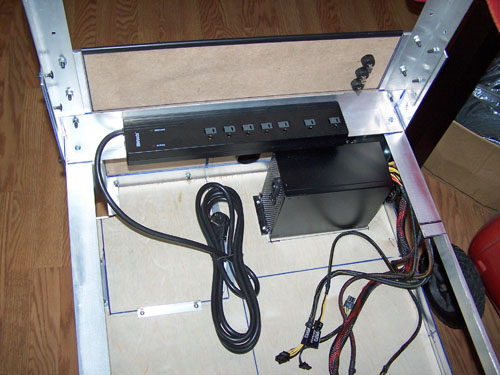
Below shows where the surge protector will be
installed, I will use the heavy duty double stick tape to hold it in
place. The biggest selling point for this surge bar vs. what I
was going to use... it has a 10 foot cord.
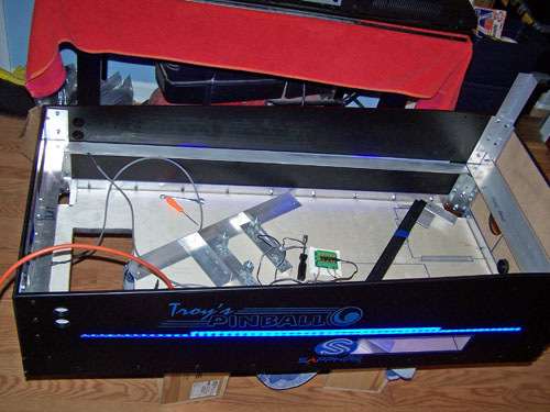
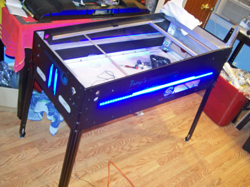
I installed both of the side panels and then finished
with the front. Once it was all together I couldn't resist
plugging it in to check out the lighting.
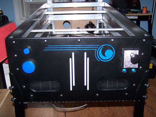
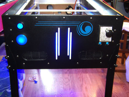
Here is a look at the front, it looks good and I had
no idea at this point, but I had the legs installed and started
putting the front together when I realized there was a problem.
The plunger is too long and sits too high, as such it
is directly in the way of the TV, the plunger will need to be
relocated lower on the panel... below is a freshly cut new front
panel.
I used four screws and large washers to hold the old
front panel securely on top of the new one, it is now just a nicely
painted hole saw template.
Fast forward and the new panel is cut, masked off and
ready for vinyl color.
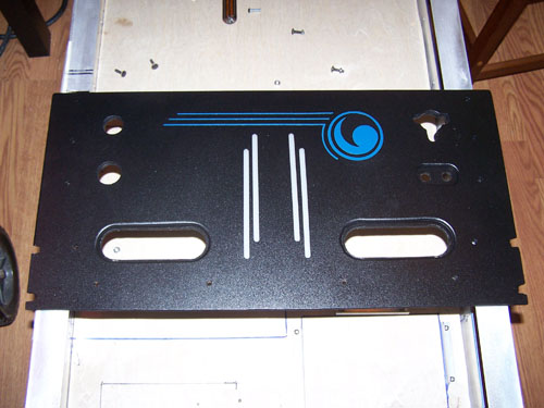
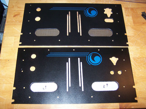
I took the redo as an opportunity to fix a few things
I wasn't happy with, the top panel in the picture below is now scrap
and is only shown for comparison. I cleaned up the plunger
hole and put the buttons below the plunger back into two separate
holes, I also made the left side lower button hole smaller and fixed
the edges of the speaker holes.
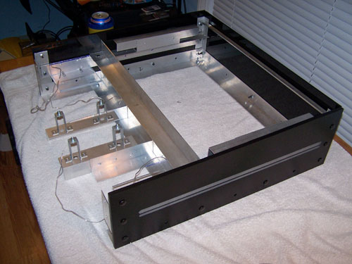
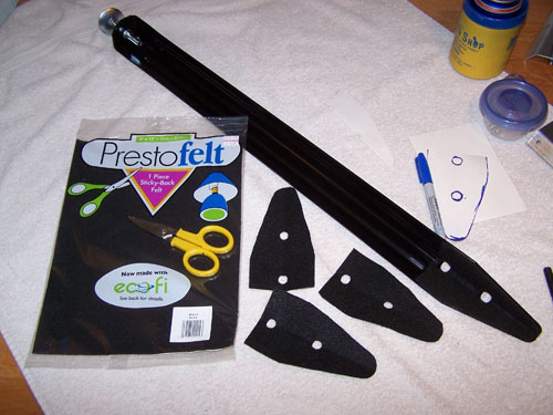
Next up are the legs, I could have just bolt them on
the way they were but I want to make sure that the legs won't
scratch up my machine over time. Below shows what I came up
with...
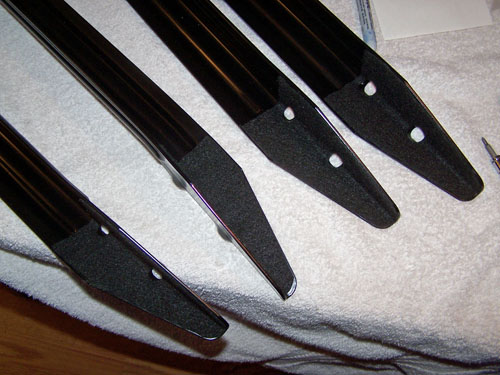
Here are the four table legs, all felt up and ready
to go. I installed the legs, it looked so cool I decided to
set the 40" HDTV into the cabinet, and that looked so cool I decided
to start putting hardware onto the front panel starting with the
plunger.
Mounting the legs was no easy feat, dipping the bolt
threads in petroleum jelly finally helped them go in easier.
With all four legs installed it is actually starting to look like
something...
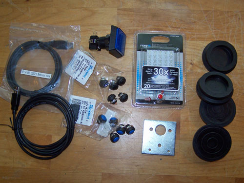
I bought a few more parts for the pinball machine,
two 6" USB extension cables five blue and five black SPST NO
buttons, a 1.5" square blue LED pushbutton, a twenty LED automotive
dome light, a metal plunger back plate and four rubber feet.
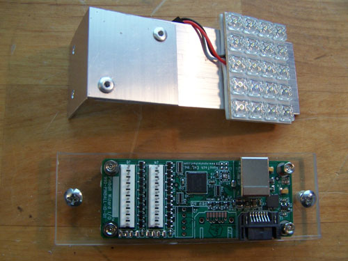
I rivet together a couple pieces of aluminum angle
and attached the 20 LED dome light to it at the level of the side
Sapphire logo, below it is the acrylic mount I made for the Pinball
Wizard PCB.
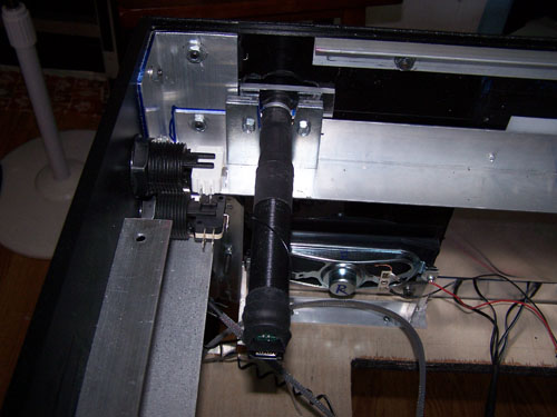
I had to modify the metal plunger back plate and a
few pieces of acrylic to mount the plunger. I also installed
the side buttons and the front speakers.
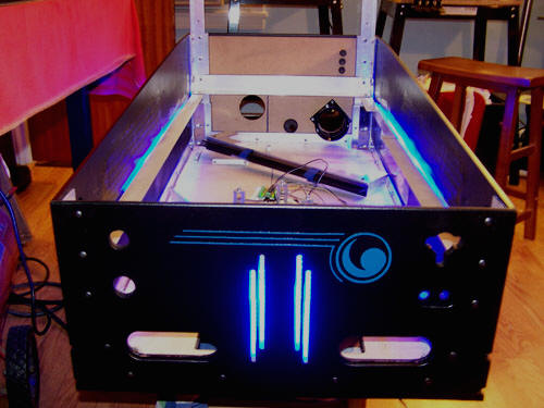
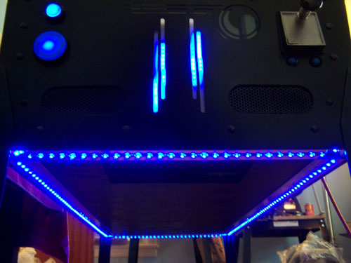
Below is a shot of the front, I installed SMD LED
strips to the underside edge of the table all the way around.
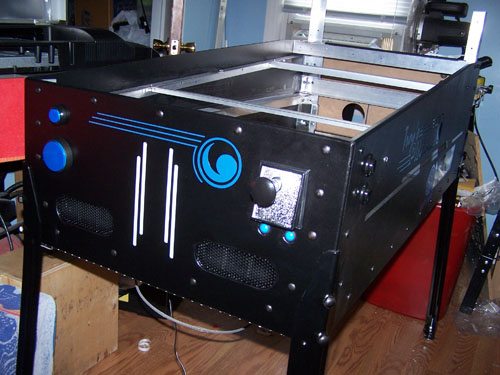
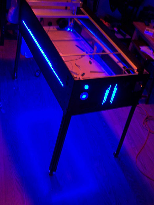
Here is a 3/4 view, ignore the wiring hanging out the
bottom, it will all be neatened up closer to the finish.
Next up, another LED test video...
The front blue LED button and LED jumbo push button
are wired to power.
I didn't like that when standing and looking at the
machine the LED strips I installed on the table underside were
visible, moving the strips back an inch did the trick.
In a darkened room the blue glow under the machine is
pretty intense...
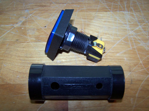
The black tubular thing below the
blue square push button is an arcade push button wrench, it only
cost a couple bucks and for getting buttons fit tight it's worth every
penny.
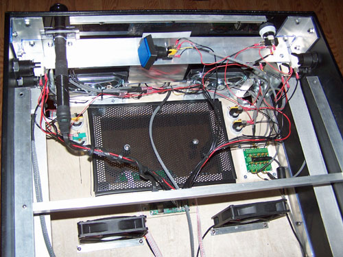
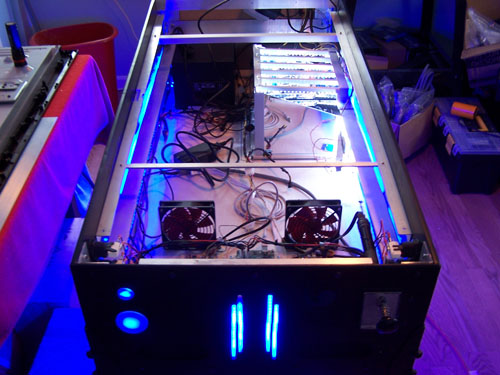
In the following picture I have all of my buttons and
plunger wired to the Pinball Wizard/Mot-Ion controller, I also
installed four push buttons into the bottom of the machine and wired
up the square blue push button. Two 120mm fans were installed
in front of the freshly meshed bottom vent/access hole
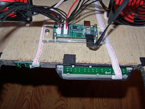
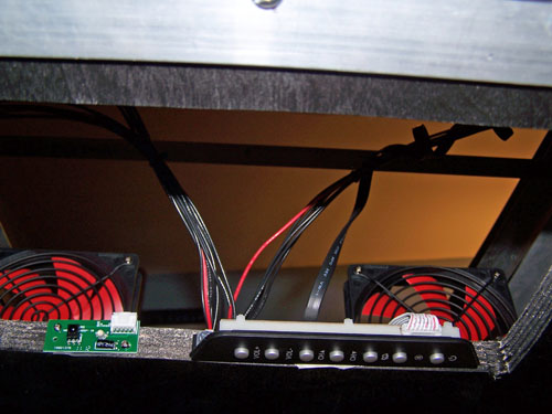
The TV controls were mounted on the inside edge of
the front access/vent hole, beside the TV hand controls sits the IR
remote receiver/power LED PCB.
Here is a bottom up shot of the TV controls and
remote control PCB.
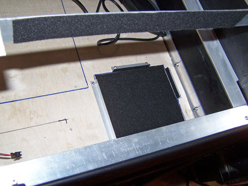
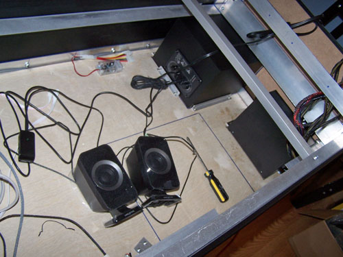
I cut a length of adhesive backed felt to line the
back brace where the 16" monitor face will rest, the
area under the sub woofer and any piece of aluminum angle that makes
contact with the sub woofer were also lined with felt to prevent unwanted
vibration.
The sub woofer and power supply are installed...
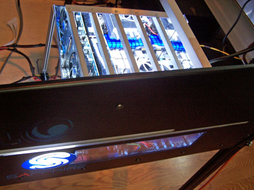
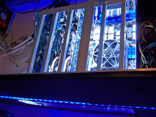
Motherboard, video cards and lighting are wired
and installed. There are three separate lighting elements that
make up the Sapphire window effect, two are shown below and one
still has to be wired, each has it's own on/off switch on the back
of the machine.
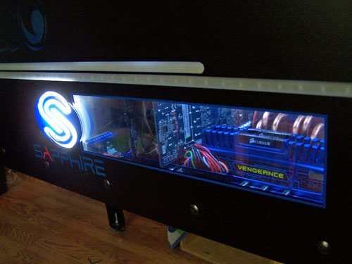
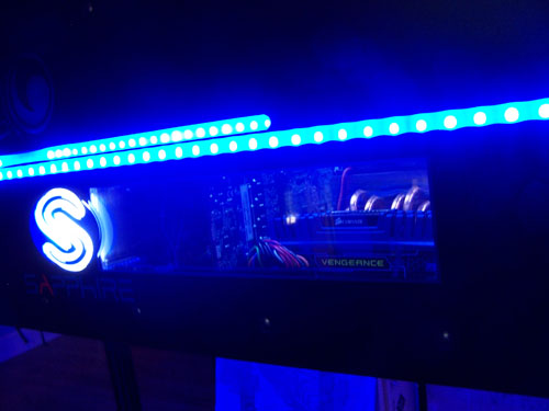
Here is a nice shot of the window...
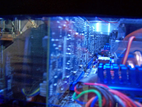
Here's why two-way mirror was used, the
video cards reflection in the picture below appears to go on
forever.
I turned on all of the blue SMD LED strips to make
sure they would not interfere with or over power the window.
The blue LED strips and window lighting work really well together...
It's starting to fill up with hardware, other than
the 40" TV the table part is fully assembled and ready for some wire
management.
I almost forgot to show that the Sapphire window is a
mirror when the backlighting is off...