I am happy to announce that
Sapphire is on board as
an official hardware sponsor for this build, I will be incorporating
an illusion that showcases their hardware into the pinball table to
thank them for being so awesome.

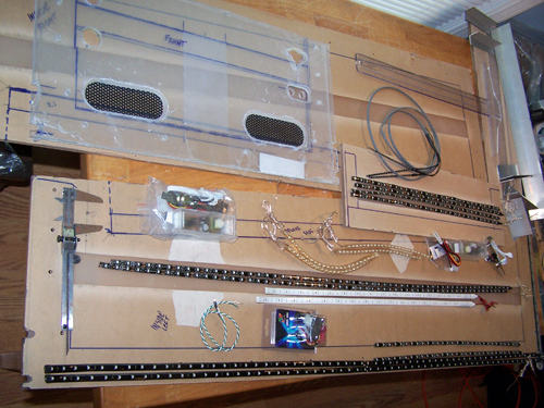
Below shows most of the 600+ LEDs that will be used
in the build all laid out one last time to determine final
placement. I decided that the two 44" SMD LED strips and two
of the 19" SMD LED strips would be better used to shine from the
table bottom onto the floor beneath, and to connect two of the 19"
SMD LEDs that go up the sides of the back glass to sound activation.
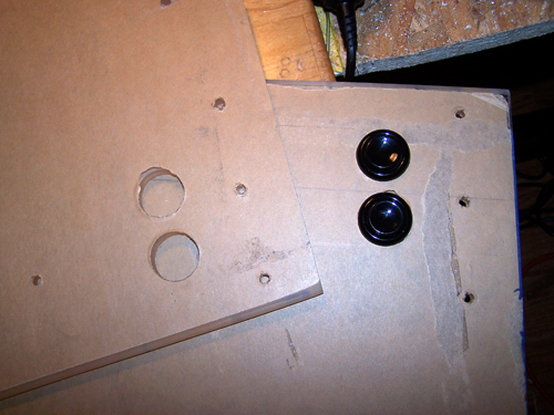
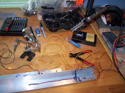
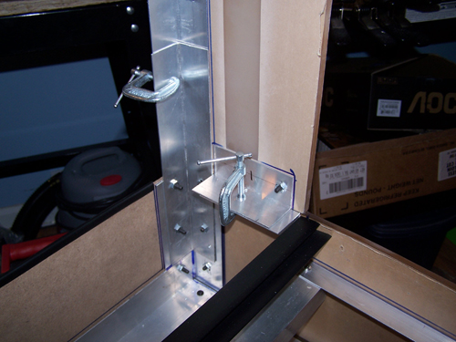
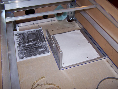
I carefully measured and then drilled all of the
necessary holes into both side panels, now the Alum-angle frame for
the 40" LCD has mounting holes and there is an Alum-angle support
piece for the back box. Last but not least I used a hole saw
and cut out all four of the flipper button holes, below are a pair
of buttons test fit.
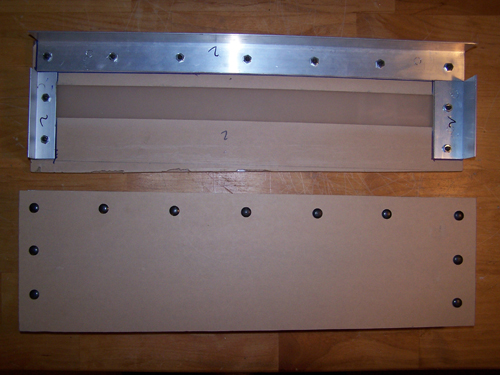
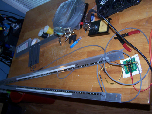
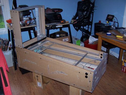
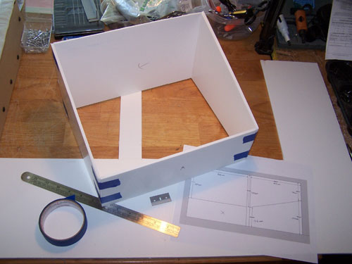
The bottom part of the table is almost ready for
paint, next up are the side panels of the back box. Below is
an opposite side view of both sides, I installed Alum-angle onto all
of the side edges except the front.
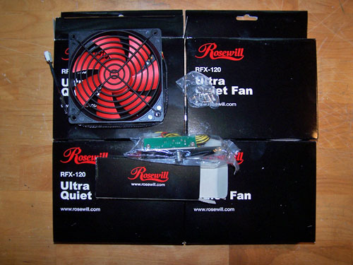
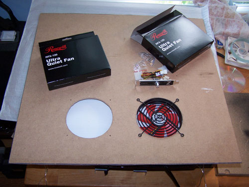
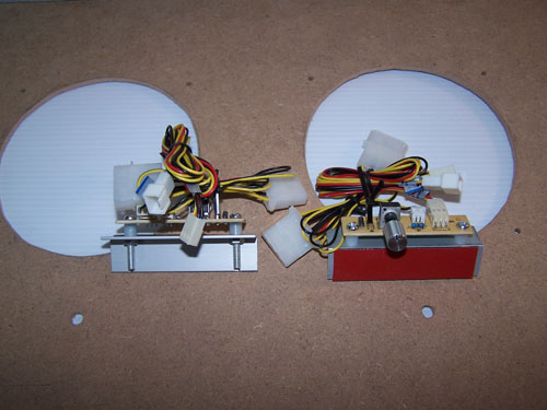
I found a great deal on four 120mm fans, they were
seven bucks apiece with free shipping and come with a black fan
grill, mounting screws and a fan controller, on top of that they
look nice.
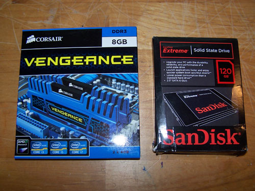
I bought 8GB of DDR3 and a 120GB SSD that is supposed
to be whip quick according to everything I've read about it.
I am pleased to announce that
AMD
is officially on board as a hardware sponsor and want to thank them for supplying
my digital pinball project with a sweet quad-core
Zambezi processor.

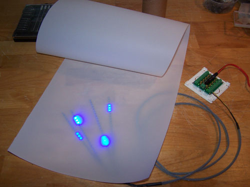
The 36" roll of light diffuser film I ordered
arrived, I am going to put it between the acrylic and the LED strips
to help spread the light out. The following picture shows the
test fire and it gives a good view of how it looks live.
I drilled a couple holes in the back sides of the
alum-angle side braces to allow the wiring from a pair of SMD LED
strips to poke through, then I soldered the wires together onto
longer wires.
Below are the finished products all wired and
sleeved, both are now ready to be installed.
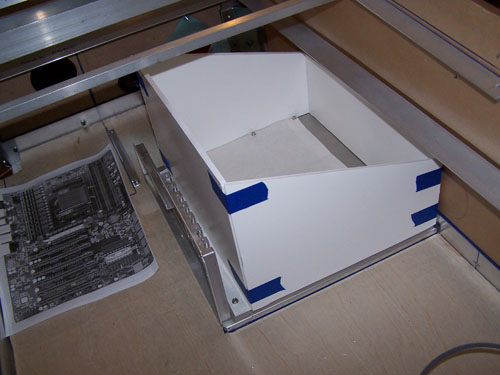
Time to build and attach the back box... I used a
couple C-clamps to hold the side panels in place and then marked and
drilled the attachment holes.
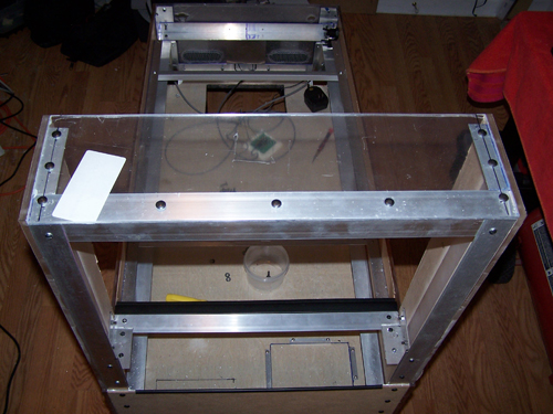
With the back box attached and the fresh cut top
panel in place for a test fit, it is finally starting to look like a
pinball machine.
Here is a look at the attached top panel from behind
the machine, below it is a length of alum-angle attached to the
black plastic trim piece that will hold the playfield glass in
place.
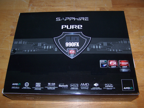
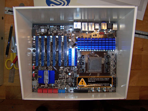
The Sapphire sponsored hardware arrived, the PURE
Black 990FX socket AM3+ motherboard is shown below. I have
been building computers since the late 90's, so I didn't have to
look at this motherboard for very long to know that it's top tier
with a switchable dual bios, post code readout and built in power
and reset buttons, good stuff.
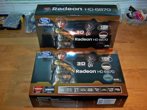
Sapphire also sent a pair of Radeon HD 6870 cards...
any fears I had about the hardware being too underpowered to run
Virtual Pinball, Future Pinball or HyperPin with every bell and
whistle enabled are now history.
Sapphire is awesome and it would be a crime to hide
away the killer hardware powering my pinball table, so I am going to
work a window into the side with their logo on the outline, I'll
also be building a mirrored enclosure inside the table to showcase
the hardware within an optical illusion.

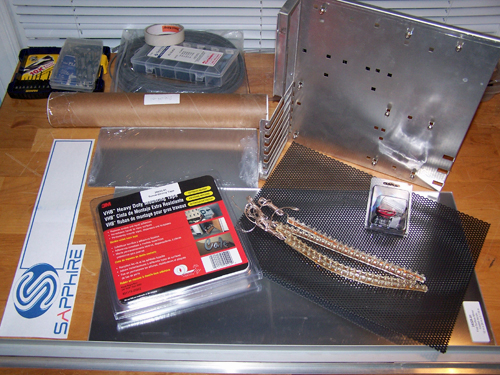
The parts needed to create the mirror illusion are
shown below, clockwise from top right is a cut down Lian Li
motherboard tray, black plastic mesh, white lazer LED, four 12v
white LED strips, 12" x 24" sheet of 1/8" first surface mirror,
Alum-angle, 3M heavy duty mounting tape, paper Sapphire template, 6"
x 12" two-way mirror, 12" x 36" light diffuser film roll.
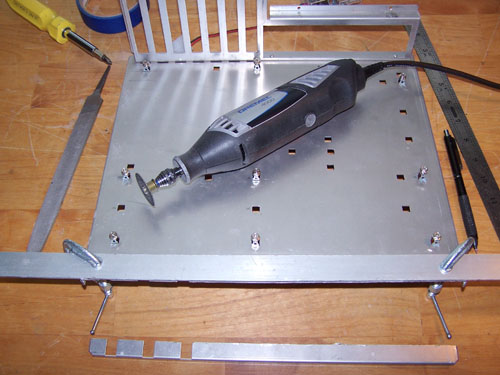
The motherboard tray was too large, so I measured
things out and then used a Dremel to cut off the excess bit.
Clamping down a piece of flat aluminum angle protects the surface
and makes the cutting easier by allowing the cutting disk to butt
against it, which keeps the edge cleaner and straighter.
I needed to find the proper location for the
motherboard and window, once that was figured out I taped down the
window template.
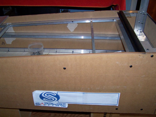
Below shows placement of the motherboard tray, having
hardware in hand let me know that there are a few aspects of the
mirror illusion design I still need to work out. They are
small details and I will figure it out, but until then there is
still work to be done on the back box.
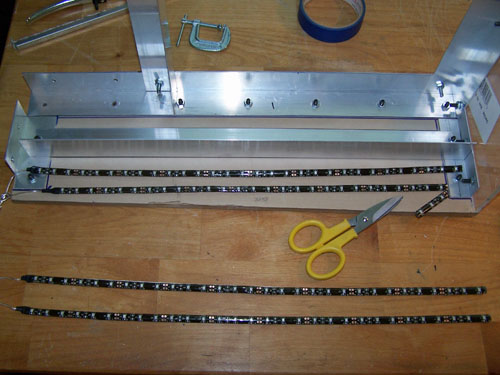
The SMD LED strips that I bought for the sides of the
back box were just a bit too long, luckily they can be cut at every
third LED (as shown below), so crisis averted.
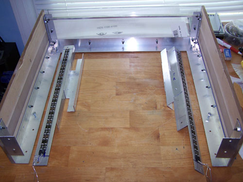
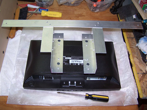
I installed two SMD LED strips onto the left and
right side pieces of aluminum angle, I also rivet on support pieces
for the 23" LCD monitor and cut 3 1/2" out of the bottoms of the
angle to make room for the speakers.
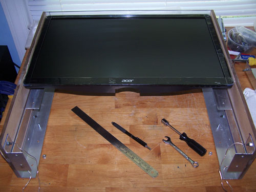
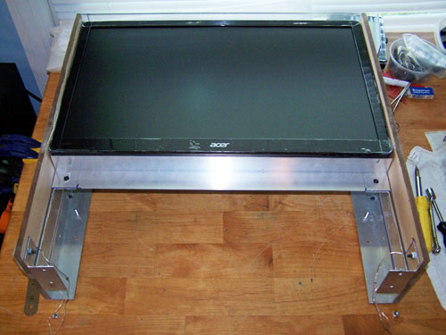
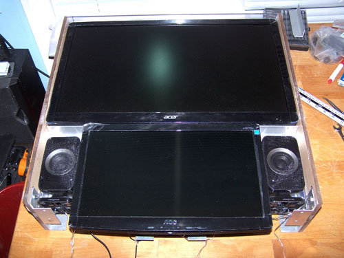
Below is the 23" LCD monitor test fit onto the side
support braces, since this monitor isn't VESA mountable it will be
held in place with 3M heavy duty mounting tape.
It will also be held in place by an aluminum angle
support brace on the bottom, the brace sits just beneath the edge
mounted monitor control buttons, so they are all still fully
accessible.
The 16" LCD monitor is VESA compatible, but I almost
wish it weren't because 3M mounting tape would have been a lot
easier than the home brewed VESA rigging I built for it.
This next picture shows how my Franken-VESA mount
attaches to the back box, the four LCD attachment points are
actually recycled bits from the 40" HDTV I tore down earlier.
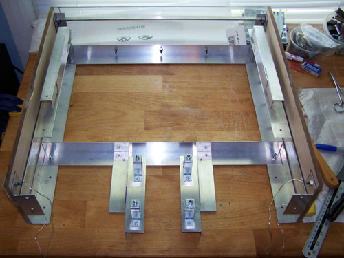
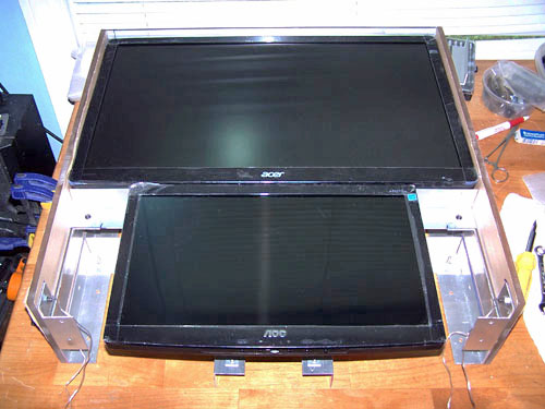
Both monitors are shown test mounted below, since the
front of the back box has a tapered edge the important and difficult
thing is keeping everything lined up straight and even to the front
edge.
To mount the speakers I cut a piece of aluminum angle
slightly smaller than the height of the speaker and then cut a piece
of 1/4" acrylic the same length as the alum-angle but slightly wider
than the speaker and used two screws to hold it together, it is
mounted onto the back box side aluminum angle with four rivets.
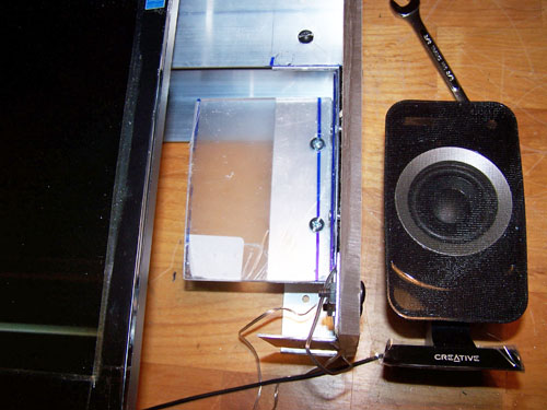
I will either use 3M mounting tape or Weld-on 16 to
attach the speakers to the acrylic mounts I made. By cutting
the bases off of the speakers I can get more left/right, up/down
movement to better center them, unmodified the speakers sit tight to
the 16" LCD monitor and level to the front edge as shown below.
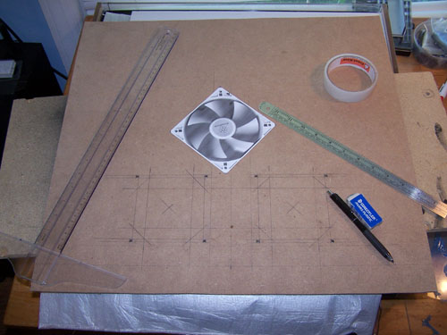
I cut a piece of MDF pressboard to fit the back side
of the back box, then I measured out placement for two 120mm fans
near the top of the panel.
I used a Dremel to cut the holes and then cleaned up
the edges with a Dremel sanding bit, below shows a fan test fit and
the fan controller that still needs modification.
I drilled an 1/4" hole in the pressboard under each
of the 120mm fan holes to accommodate the fan control knob posts,
the following picture shows the new improved mounting method.
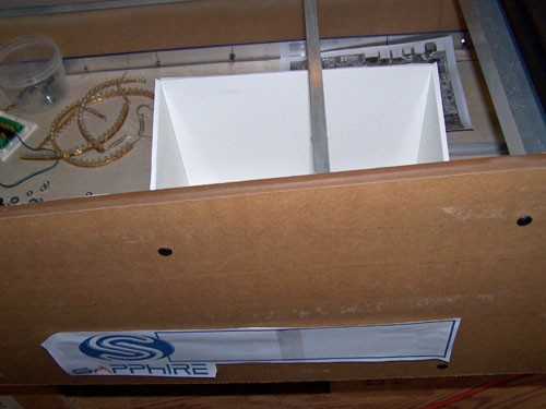
Time to get back working on the Sapphire illusion,
the first thing I did was make a mock up to get a better idea of how
things will work. I made a design in Sketchup, bought a piece
of foam backboard, then measured, cut out and taped together the
four panels.
Next the panels are test fit to the motherboard,
which looks sweet...
Then the panels get test fit inside the pinball
table, which fits sweet...
And the panels get test fit to make sure the position
of the window decal template is correct, it lines up sweet...
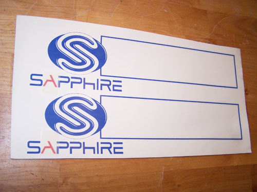
I took my Sapphire window design to
Agnew Graphics, a local sign
company, the price was reasonable and they did a good job cutting my
design fast... and they even gave me a second (mulligan) decal free.
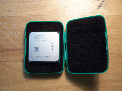
AMD came through as well, the sponsored FX4170
processor arrived via FedEx today and it came housed in a sweet
little green case, so big thanks go out to them.
Troy's Pinball Build Log Page 4