|
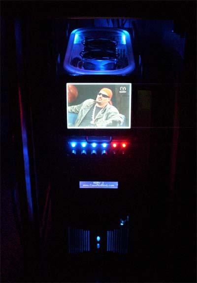
SINGLE 5.25" BAY 6" LCD MOD The single bay LCD design was a hit and miss adventure (with a lot more miss than hit) and it took me three tries to get it right. I winged it, and eyeballed a lot of the measurements, thankfully my eyes were right and my wings ended up getting me there. I only mention this because background can be important, me letting you know what was involved leading up to the finished mod could wind up helping you, mainly because I have no solid measurements and I don't have a lot of progress pictures either. Taking pictures was really slowing down the "design as you go" process and after design one crumbled I was finished playing nice and definitely wasn't bringing my camera into it I looked at SoulsEnds original idea and made it my first attempt - minus the hinges he used - but with the screen sitting face down the tracks I had made for it to slide on wound up scratching the screen... dammit. I didn't want the screen face pointing down anyway (as in his design), since I have a top window in my case it would have to show through when the bay LCD monitor was closed, so this posed yet another design hurdle. Revision 2 is not even worth talking about and after a week of failures I was at another starting point. Revision 3 luckily wound up being the ticket and the planning for it mostly occurred as I walked around an ACE Hardware store, all the parts for this mod other than the LCD screen and handle were in fact purchased at ACE Hardware.
The first hurdle... I bought the 6" LCD monitor thinking that it would not only fit "no problem" into a 5.25" bay, but that it could also be motorized it to make it eject... wrong. It was too wide to even fit into the bay and there were wires that stuck out of the side making things more problematic, so much for my first idea. Time to concentrate on just making it fit, everything that is holding it back must be either removed or moved, fun. The second hurdle... Once it fits into a bay it still has to come out with the face of the monitor pointing up, I can't have the LCD PCB backside showing through my top window, it's not an option because it's not up to CMG standards... if you have a top window and an LCD monitor in the top bay it must show through the window = law. OK, now that we know what we are up against we just have to make it happen. I will save you a lot of hassle and not write the guide in the manner that I accomplished the mod, instead I will try to make things as easy as possible and hopefully keep your little LCD screen alive in the process. I came up with a track mount slide out idea that allows the LCD to do everything in the manner I intended. Tthough the design was not entirely problem free it does work splendidly and will be the way we do this mod. We first need to mod the LCD by removing the excess side metal and also reposition the side wiring so that it will even fit into the bay.
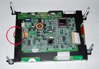
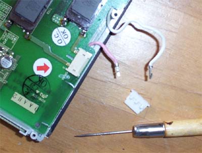
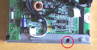
The above circled spots show the wiring that needed to be moved, it sticks out too far from the edge for the monitor to fit. I also used a nibbler to remove the extraneous side black metal that was making things too wide, right up to the screws that hold both halves together and then filed it all smooth. Remove the four screws that hold your screen together and carefully split open your LCD like a clam, I put some paper towel under the screen side to help prevent scratches.
I pulled the wiring clip from the side of the screen and removed the clip housing from the wiring.
I used my electricians scissors to remove the clip housing material to make room for the wiring, I removed too much material which made one of the metal contacts separate, figures that the plastic housing was what held it all together... not good. One drop of superglue and a small clamp luckily fixed it. I then soldered the wiring directly to the pins.
Next, the LCD slide rails need to be cut from some 1/16" x 1/2" ALUM - ANGLE.
Cut them as tall as the screen is and then cut out the sections of ALUM - ANGLE into the shapes shown below. A nibbler and a file made short work of this. You might as well drill the holes in the rails, mark the holes to the LCD screens metal plate and carefully drill them too while the screen is split open. The red circles show where I drilled holes, four to hold the rails on and one on the bottom to keep the wiring together. I tried to locate the holes where they would not interfere with anything and also be easiest to work with.
Below is a close up of the right side rail, the material around anything that stuck out (ie. ribbon cable, PCB) was marked onto the rail and the aluminum was removed.
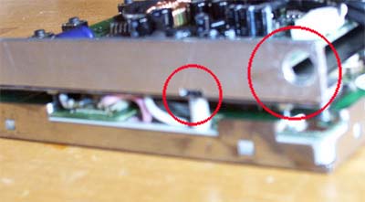
Below is another close up picture showing the cut out metal for the left side rail, the circled screw in the hole was a bear to get in.
You will also need to drill a hole into the ALUM-ANGLE (circled) on the side where the screen bottom will attach to the slide bar and face plate. The other circle shows the filing I did to try and make the aforementioned "bear" screw fit easier.
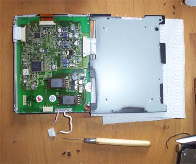
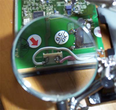
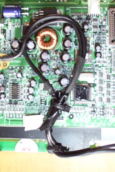
I learned this the hard way... below is the optimal wiring configuration for the backside of the LCD and it keeps the wiring from getting caught up when sliding in and out. If the screen does not come out easily DO NOT force it, the white clip in the bottom of the picture is cockeyed because I had to bend it back into shape after being impatient about the screen not coming out correctly and damn near shearing the whole thing off.
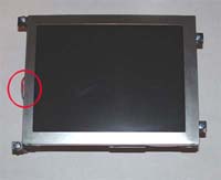
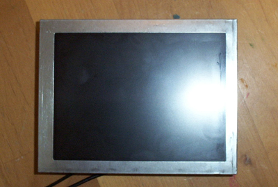
Here is another screw-up... If you look at the shot of the screen below you can clearly see a scratch up the right hand side of the screen caused during revision one, it won't even be noticeable when finished.
Now that the LCD part of this is finished and all modded proper we have to work on the tracks that the LCD assembly will ride on inside of the case. |
|
|