|
The Project, Continued: (You may click on a picture to view a larger version)
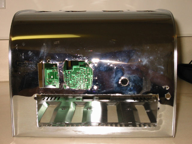
Here are the holes I have cut in the backside of the toaster. Starting from the top left: Power cord for PSU, Fan cut out for PSU, and the round hole is for the USB TV Card. On the bottom we have the cutout for the motherboard, and the 2 holes on the right are for the wireless 802.11 NIC and its LED.
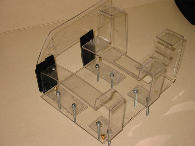
Now we can start to assemble the computer. I purchased Lexan acrylic sheets for my computer as it bends when cold. I cut the Lexan with a jigsaw using a very fine tooth blade at a low speed. The Lexan is hard to bend, but once the bend is started it moves very easily. In this picture you can see the motherboard tray (bottom shelf), the Hard Drive holder (vertical supports in back), the DVD tray (vertical support on left side), and accessory shelves (the 2 cross members that run left to right). I had to make a hump in the accessory trays so that my wireless network card would fit.
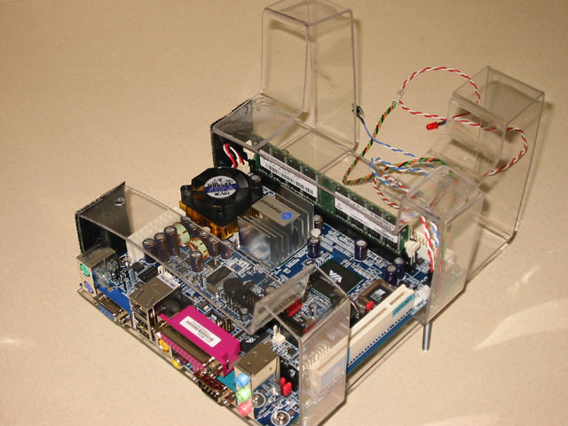
Here we see my brand new Via M9000 motherboard installed with the power switch, Hard Drive LED, and Power LED in the background.
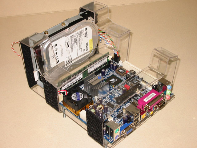
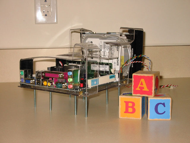
This is the motherboard and Hard Drive installed in the Lexan cage.
This is my obligatory size comparison shot. These are my daughter’s wooden blocks and in the background you can see a power outlet. |
|
|