|
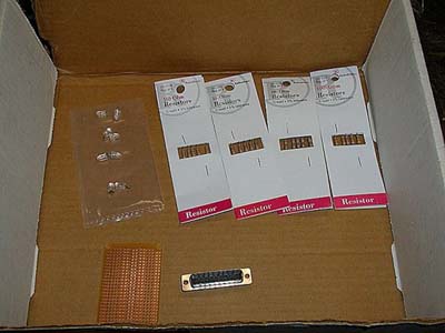
LED Meter Guide The LED meter is a rare mod that is used by only the most daring (read: can kill a parallel port) or well funded case modders. This mod uses the printer port to transmit data to an array of 8 LED's, making them do whatever the user can find or write a program for. From WinAmp sound movement to system use, the possibilities are limitless. This guide will show you how to make an affordable and safe meter so you to can have one of the most visually entertaining mods ever made. The most common application of the LED meter is for WinAmp. Using a visualization plug-in, music output can be displayed on the meter in 2 different ways- Boom indication (vertical meter), which indicates parts of the music rich in bass or when all the instruments hit a beat at once, and Music illustration (horizontal meter), which is the same effect as the equalizer visualization, only on your LED meter in your case. The meter can also display various system usages from CPU time to network usage to CPU temp. For this mod, you will need:
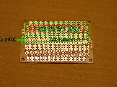
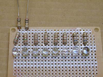
The Board: You will first want to place your LED's along the board, taking full use of the built-in ground bus, or making your own.
You will want your components on the plain or white side. Your anode (longer lead, positive) will go into the individual rows, while your cathode (short lead, negative) will go into the ground bus. You will want your colors to range from a blue/green spectrum to a yellow to red, or another bright color to alert you to high levels.
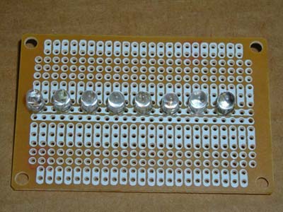
LED's in place. Time to solder in the resistors. MAKE SURE YOU SOLDER THE RIGHT RESISTORS TO THE RIGHT LED'S. Failure to do so will result in wasted time and money (dead LED's).
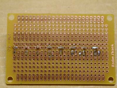
160ohms is a hard to find (if existent) resistor, so I soldered a 150 and 10 in series. Notice how the board design goes so well with the mod.
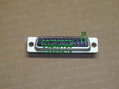
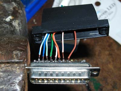
Now your board is essentially done. Next we will move on to soldering into the DB25 connector. This process is fairly simple. Make sure your solder points are strong because this part will receive a bit of punishment if you are switching between the meter and a printer, or if you want to unplug it at night (like me). You should always have a hood for your connector too. This will prevent stress on 1 particular solder point and will also prevent short circuits. NOTE: If you are using CAT5, be warned that it is extremely hard to strip unless you have uber1337 wire stripping skills with your fingernails, a knife, or some special order wire strippers. Also, you will need 1 additional wire for your ground. On the DB25 connector, we will be working with pins 2-9 and 25. The bottom channel will go on pin 2, the next on 3, etc up to 9. The ground will go on pin 25. See the diagram below for pin locations.
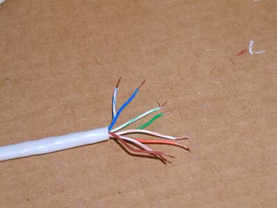
Now we need to prep our cable for soldering. When using CAT5, you can separate the pairs into pairs for your LED colors (assuming you used 4 colors). This worked great for me because I could use blue for blue, green for green, orange for yellow, and brown for red.
I used the color-white for the lower LED of that color, and the solid for the upper LED. Make sure you put your hood on BEFORE soldering.
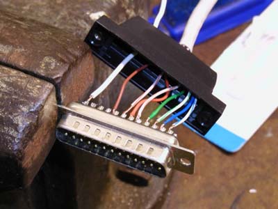
Now flip the connector and solder your ground.
|
|
|